Table of Contents


- Following settings is valid for Gremsy Firmware v7.5.4
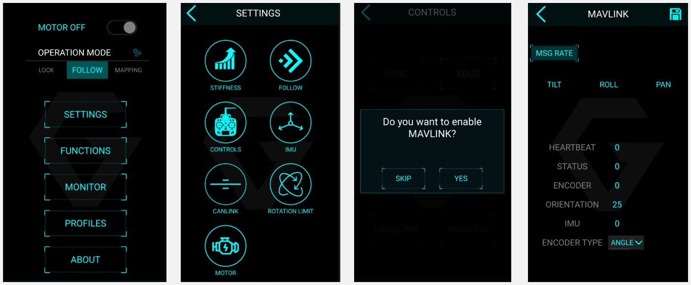
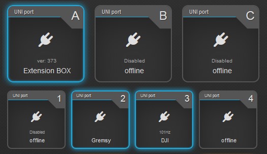
- Power on the Gimbal and connect the gTune application to the gimbal via BlueTooth or WiFi
- Click to SETTINGS -> CONTROLS -> Confirm YES
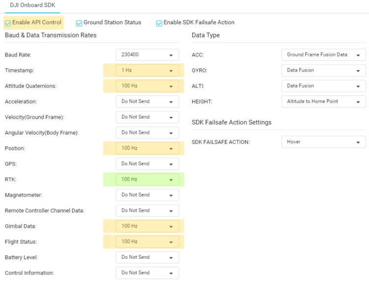
- Set MSG RATE of all to 0 only ORINETATION set to 20 (20Hz)
- Once configuration is done, you can switch back for SBUS or LightBridge control method (LB2)
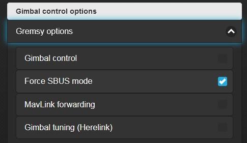
- If you would like to use LightBridge (LB2) control mode via CAN, enable “Force SBUS mode” feature in the Entire’s MENU under Gremsy options same as for SBUS mode.