Do not mismatch this page with control of the Entire via SBUS. Follow this page for SBUS control of the Entire.
This page is about SBUS OUT feature of the Entire. This is used for usage scenarios, where Entire generates SBUS signals for camera control. SBUS OUT can be of course freely used in many scenarios, however mainly is used for Wiris camera control.
SBUS generated by the Entire itself (PORT B), you need special cable which inverts signal from the Entire. This cable is available at our store.
SBUS OUT generated by Extension BOX port UNI-1
In this case you have to use default SBUS cable (same as for SBUS input). This is more elegant solution, however in some cases may cause wiring issue, as Extension BOX is usually located at the drone body.
Navigate to Entire’s MENU, select Control mode. In new window select “SBUS out“.
In this mode will the Entire all received commands (does not matter how, AIR Commander Link, MavLink (MavCam) or SBUS input) execute as change in SBUS out channel.
STEP 2
Enable SBUS OUT mode at port UNI-B or UNI-1 and use cable as per this text. Now the Entire generates SBUS signal at selected port and receiving device should “see” incomming SBUS signal with all channels in the center position.
STEP 3
Now you need to define, which channel of the SBUS OUT should “move which way”, when some function of the Entire is triggered.
Navigate to Entire’s MENU, select Miscellaneous, then “SBUS out mapping“.
You will see list of channels of SBUS OUT signal.
STEP 4
Following settings needs to match controls of the camera (or other controlled device).
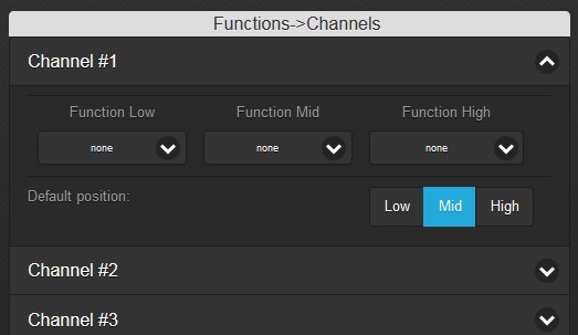
Each channel has three asignable functions:
Function LOW
Function MID
Function HIGH
Each channel has also setting of default position:
LOW
MID
HIGH
EXAMPLE
In this example (photo at right), Channel #1 of SBUS OUT signal is:
By default in center (settings MID)
When user triggers PHOTO, channel #1 will get LOW for approx. quarter of second. Then it returns back to default – center position.
When user triggers VIDEO, channel #1 will get HIGH for approx. quarter of second. Then it returns back to default – center position.
Do not mismatch this page with control of the Entire via SBUS. Follow this page for SBUS control of the Entire.
This page is about SBUS OUT feature of the Entire. This is used for usage scenarios, where Entire generates SBUS signals for camera control. SBUS OUT can be of course freely used in many scenarios, however mainly is used for Wiris camera control.
Enable SBUS OUT
There are two options of using SBUS OUT control:
SBUS OUT generated by the Entire port UNI-B
SBUS generated by the Entire itself (PORT B), you need special cable which inverts signal from the Entire. This cable is available at our store.
SBUS OUT generated by Extension BOX port UNI-1
In this case you have to use default SBUS cable (same as for SBUS input). This is more elegant solution, however in some cases may cause wiring issue, as Extension BOX is usually located at the drone body.
Using SBUS OUT control
STEP 1
Navigate to Entire’s MENU, select Control mode. In new window select “SBUS out“.
In this mode will the Entire all received commands (does not matter how, AIR Commander Link, MavLink (MavCam) or SBUS input) execute as change in SBUS out channel.
STEP 2
Enable SBUS OUT mode at port UNI-B or UNI-1 and use cable as per this text. Now the Entire generates SBUS signal at selected port and receiving device should “see” incomming SBUS signal with all channels in the center position.
STEP 3
Now you need to define, which channel of the SBUS OUT should “move which way”, when some function of the Entire is triggered.
Navigate to Entire’s MENU, select Miscellaneous, then “SBUS out mapping“.
You will see list of channels of SBUS OUT signal.
STEP 4
Following settings needs to match controls of the camera (or other controlled device).
Each channel has three asignable functions:
Function LOW
Function MID
Function HIGH
Each channel has also setting of default position:
LOW
MID
HIGH
EXAMPLE
In this example (photo at right), Channel #1 of SBUS OUT signal is:
By default in center (settings MID)
When user triggers PHOTO, channel #1 will get LOW for approx. quarter of second. Then it returns back to default – center position.
When user triggers VIDEO, channel #1 will get HIGH for approx. quarter of second. Then it returns back to default – center position.